Homebrew RF Attenuators: Pi and T Pads on Copper Clad
 In my last
post I mentioned using a homebrew 23dB
attenuator while aligning the BFO on my 20m rig. I had previously built a
couple of them, in both pi and T configurations — a 23 dB T pad and a 46 dB pi
pad. I found these to be really useful, over and over. They’re great for
injecting test signals and protecting sensitive inputs. They pair well with
tools like the NanoVNA and tinySA for all manner of homebrew work. And they
cost almost nothing to build.
In my last
post I mentioned using a homebrew 23dB
attenuator while aligning the BFO on my 20m rig. I had previously built a
couple of them, in both pi and T configurations — a 23 dB T pad and a 46 dB pi
pad. I found these to be really useful, over and over. They’re great for
injecting test signals and protecting sensitive inputs. They pair well with
tools like the NanoVNA and tinySA for all manner of homebrew work. And they
cost almost nothing to build.
You just need a few resistors, a couple of SMA connectors (or BNC if you prefer), and a scrap of copper clad board. The result is a compact, reliable 50 ohm attenuator that performs well. For HF, carbon film resistors are fine. If you are planning to do VHF, metal film resistors are a better choice, although my pads work fine on 2m.
Why Two Topologies?
Both the pi and T attenuator are resistive pads that present 50 ohms on both ports. They differ in how the resistors are arranged, but for a given attenuation value the performance is essentially identical. The choice between them comes down to which resistor values you have in your junk box, or which layout suits your scrap of board better.
A pi pad has a shunt resistor on each side of a single series resistor — the schematic looks like the Greek letter π. A T pad is the mirror image: a series resistor on each side of a single shunt resistor to ground, forming a T shape.


For a symmetrical attenuator (same impedance on both sides), the two shunt resistors in a pi pad are equal, and the two series resistors in a T pad are equal. This simplifies the build because you only need two resistor values for either topology. In our case, we’ll double up some resistors so we can use readily available values.
The Math
The formulas for a matched 50 ohm attenuator are well documented. You don’t need to use them; I’m going to show a table of values. But if you enjoy the math, or you need to compute different values, here they are.
Let Z₀ = 50 ohms and let the desired attenuation be A dB. First compute the ratio:
K = 10^(A / 20)
Pi pad:
R_series = Z₀ × (K² - 1) / (2 × K)
R_shunt  = Z₀ × (K + 1) / (K - 1)
T pad:
R_series = Z₀ × (K - 1) / (K + 1)
R_shunt  = Z₀ × 2 × K / (K² - 1)
For quick reference, the table below picks whichever topology lands on the most common resistor values for each attenuation level. Where a value is shown as “2 × R”, that means two resistors of value R in parallel to get R/2. The attenuation figures are approximate — using standard values shifts things by a fraction of a dB, but the impedance match stays close to 50 ohms in all cases.
| Attenuation | Topology | Series | Shunt |
|---|---|---|---|
| ~3 dB | T | 10 Ω | 150 Ω |
| ~6 dB | Pi | 39 Ω | 150 Ω |
| ~10 dB | Pi | 2 × 150 Ω (75) | 100 Ω |
| ~20 dB | T | 39 Ω | 10 Ω |
| ~23 dB | Pi | 390 Ω | 56 Ω |
| ~46 dB | Pi | 4.7 kΩ | 2 × 100 Ω (50) |
Note that I did not include the 23 dB T pad in the table because I used a non-standard value.
You’ll notice both pi and T topologies appear. I’ve selected the topology that has the easiest resistor values for each attenuation level. At low attenuation, T pads tend to use rounder values; at high attenuation, pi pads win because the shunt resistor converges toward 50 ohms (easy to hit with 2 × 100 Ω) while the series resistor just gets larger. You can also cascade two lower-value pads — two 23 dB attenuators in series give you 46 dB, which distributes the power dissipation across six resistors instead of three.
Power Handling
I used 2 watt carbon film resistors for these builds. That’s massive overkill for the milliwatt-level signals you’d typically put through a test attenuator, but there’s a practical reason: 2 watt resistors have chunky leads and a body that sits nicely on copper clad. They’re easy to solder to a ground plane and mechanically robust. They also tend to have better RF characteristics than their tiny ¼ watt cousins — lower parasitic inductance relative to their size. They can also handle power levels from things like a driver amplifier, which can be useful for testing. All of my 2 watt came from a single variety pack from Amazon (Aukenien brand). If you don’t have a stock of them on hand, that’s a cheap and effective solution.
In both topologies, the input-side resistors handle the most power — the first series resistor in a T pad, and the first shunt resistor in a pi pad. With 2 watt resistors throughout, you’re well within safe limits for anything short of a QRP transmitter’s full output.
Construction
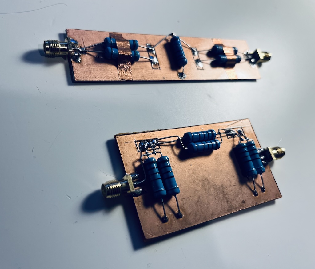
Take a look at the photo at the top of this post. The build is straightforward. I used single-sided copper clad board as both the ground plane and the chassis. The copper serves as the ground, and the SMA connectors mount at each end with their flanges soldered directly to it. I cut islands into the board with a utility knife for both the junctions and the center pin of the SMA connectors.
For the pi pad, the layout is intuitive. Solder the two shunt resistors from each SMA center pin straight down to the ground plane, then bridge the two center pins with the series resistor. Everything is short and direct. I wired this kind of fancily to keep the SMA connectors centered. You can be less fancy.
For the T pad, mount the two series resistors in line between the SMA center pins, with a junction point in the middle. A short piece of component lead or wire connects that junction to the shunt resistor, which drops straight down to the ground plane. Keep the shunt resistor’s leads as short as possible to minimize inductance. My 23 dB T pad has some copper tape over the series resistors. I found that, when scoped with the NanoVNA, the tape helped to keep the characteristic impedance at 50 ohms by adding a little capacitance. It was not necessary for the 46 dB pi pad.
In both cases:
- Use the copper as ground. Don’t lift traces or use stripboard — the continuous ground plane is the whole point.
- Solder the SMA flanges well. A good connection to the ground plane matters.
- Label them. Once you have a few, you’ll forget which is which. I mark the attenuation value on the bottom of board with a permanent marker.
The finished attenuator is small enough to live in line between two SMA cables, or to bolt directly onto a piece of test equipment.
Verification
If you have a NanoVNA, verifying the attenuator is easy. Run a through calibration, then insert the attenuator and observe the S21 trace. It should show a flat response across the frequency range — it’s resistive, so any frequency in range is fine. Look at the Smith chart for the impedance match. It cluster tightly around the center. Any deviation usually points to a solder joint issue or a resistor value that’s drifted from nominal. Double-check the SMA connectors and islands with a multimeter.
With 2 watt resistors on copper clad, I’ve found these hold up well into the VHF range, and for HF work they’re great.
Takeaway
I’ve found these invaluable. I will undoubtedly build more over time. They take minutes to build and cost nearly nothing. My 23 dB T pad and 46 dB pi pad have already earned their keep — the 23 dB unit is what I used for the BFO alignment in my last post, and the 46 dB pad is useful for injecting signals from the NanoVNA into the front end of a receiver without overloading anything.
73 de EI9ITB