A 3D Printed Reduction Drive For Variable Capacitors
 When
variable capacitors were in common use, it was easy to find mechanical
reduction drives that would allow you to more finely adjust the frequency as
you tuned across the dial. They were commonly available at 6:1, 8:1, and 10:1
ratios. You can still buy new ones today, but they’re not as common as they
used to be. And if you want to get started on a project, you may not want to
find one and then wait for it to arrive.
When
variable capacitors were in common use, it was easy to find mechanical
reduction drives that would allow you to more finely adjust the frequency as
you tuned across the dial. They were commonly available at 6:1, 8:1, and 10:1
ratios. You can still buy new ones today, but they’re not as common as they
used to be. And if you want to get started on a project, you may not want to
find one and then wait for it to arrive.
I had seen lots of interesting projects that used 3D printed gears: parts for 3D printers, parts for CNC machines, replacement parts for printers, etc. It occurred to me that this could be a really good way to make a reduction drive for a variable capacitor. So I built one.
Is it as refined and smooth as the best brass reduction drives? No, it is not. But it does work rather well. And furthermore, I have parameterized the model — you change a few dimensions and the design adjusts to fit whatever capacitor you have.
Pluses and Minuses
This took a couple of hours to print and I had it assembled in a few minutes. That’s great for homebrew projects. It also means you can customize it however you like to fit your needs. You don’t need complicated assemblies of shafts and bearings to get it lined up with the faceplate. On the other hand, it is not perfect by any means.
Other than smoothness, I accepted two other limitations: the smallest gear size, and the number of gears. In order to get something that works well, you can’t make the gears too tiny. They need to be big enough to take some abuse, and to have enough teeth to be reliable and fairly smooth. Given the resolution of most printers, the minimum size is going to have to be much larger than the tiny gears in traditional reduction drives.
Secondly, I did not want to have a complex setup. Ideally two gears and one bearing post would be all that was needed. But we’re also limited by the height of the capacitor shaft — the largest gear needs to mount on it and still have room to turn with clearance.
All of that is to say, that I could not get quite to a 6:1 ratio, which was the most commonly used. I got to a 5:1 ratio. It works great, but is not quite as finely adjustable as a brass reduction drive.
Hardware
I designed this to be printed in PLA. It’s hard, not very flexible, and works great for gears like this. Almost everyone has PLA if they have a 3D printer.
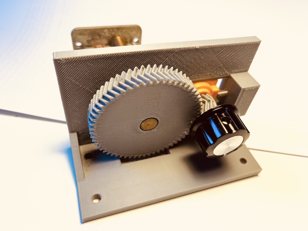
The design is simple. I used a single bearing post and two gears. The bearing post is a piece of 5mm stainless steel. I obtained a few foot long lengths on Amazon for a few euros. A hack saw and 10 minutes got me the length I needed, about 15mm for the default model. I suggest greasing the mounting end of the post because it makes the whole operation smoother. A long M4 screw is used to tension the pinion gear — that is, to adjust how tightly it’s held against the bearing post so it stays put but still turns freely. I used a stainless screw mounted directly into the PLA. This is actually better here than a metal insert because the PLA has a lot of friction on the screw (it stays set), and you will not be changing this much, so wear is not an issue.
The pinion gear has a 1/4” shaft with a flat side, as commonly used to mount knobs on potentiometers. I like the feel of injection molded knobs, but you could use a 3D printed knob instead.
Those are the only parts I used other than the PLA.
Software
I developed this in OpenSCAD, a free 3D modeling program. It has a bit of a learning curve, but it’s worth it. I’m not a CAD expert, but I’ve used it for some of these projects where parameterizing things is a real benefit. It’s also free and open source, so anyone who can edit a file can change the settings to fit their setup. That’s a huge win. If you download OpenSCAD, I suggest that you get a nightly build, as the production builds are very old and slow in comparison. The nightly build quality is surprisingly good.
If you just want to print the one I built, you can download the 3mf file here. But I think you are likely to need to change some dimensions to fit your capacitor. The OpenSCAD model file is well commented and should be easy enough to edit, even if you know nothing about 3D modeling.
Printing and Assembly
The file is set up to print, already. At the bottom you will find a section where you can comment and uncomment lines to change the layout. From OpenSCAD you need to first render it and then export it to the format you need for printing.
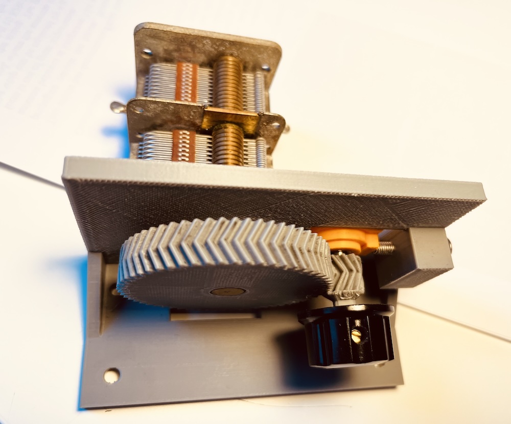
This design is intended to be free standing, for radios built on a board. The mechanism and the capacitor both need to be mounted rigidly. I suggest spending some time moving the mechanism back and forth, in order to get the teeth to mesh with each other well.
The parts all fit together as you can see in the photo. Do not grease the tensioning parts. You want to have friction hold them where you put them.
Herringbone gears have angled, V-shaped teeth that cancel out the sideways forces which would otherwise push the gears apart along their shafts. This makes them self-aligning and good at preventing backlash, which is important here because there is nothing else supporting the knob shaft. The interlocking teeth provide enough lateral support that this works better than I expected.
Next Steps
I will eventually build a version that is intended to mount to a front panel on an actual radio, and which has a support for the front of the pinion gear. If you are ambitious, or know OpenSCAD, feel free to modify it to your liking. But, if you do, please share back with me any changes you made.