Homebrew 7-Pole Low Pass Filter for my 20m Transceiver
 I built the last piece of
my homebrew 20m SSB transceiver! There is still plenty of work to do, but the
parts are now all there. The final piece was the low pass filter that sits on
the output of the power amplifier. The objective is to make the rig emissions
compliant so that harmonics are cut at the output before hitting the atmospher.
I built the last piece of
my homebrew 20m SSB transceiver! There is still plenty of work to do, but the
parts are now all there. The final piece was the low pass filter that sits on
the output of the power amplifier. The objective is to make the rig emissions
compliant so that harmonics are cut at the output before hitting the atmospher.
Why a Low Pass Filter?
A power amplifier doesn’t just amplify the fundamental frequency. It produces harmonics as a byproduct of the amplification process — signals at two, three, and more times the transmitted frequency. On 20m, the second harmonic falls at 28 MHz, squarely in the 10m amateur band. The third harmonic lands at 42 MHz. These need to be attenuated to meet regulatory requirements and to be a good citizen on the bands. A low pass filter is how you do that.
The Design
This design comes from W3NQN via the GQRP club. It is a 7-pole Chebyshev low pass filter in a capacitor-input ladder network topology — C-L-C-L-C-L-C — with a cutoff frequency well above the 20m band but below the second harmonic at 28 MHz. Pass the fundamental cleanly, and kill the harmonics. Getting that balance right is a little tricky and requires some careful tuning to get maximum performance while still maintaining the filter’s ability to eliminate harmonics.
The original design calls for T37-6 cores. I chose to wind the inductors on T68-6 toroids instead and to use 20 AWG wire throughout. My immediate plan is to run at QRP power levels — 5 watts or so — but with a larger core and heavier wire, I am leaving room to put more power through this filter later without rebuilding it. The T68-6 is a mix-6 iron powder core, well-suited to HF frequencies, and its larger diameter handles thicker wire comfortably while keeping the inductance on target. For 5W into 50 ohms, either core would work fine — but this costs nothing extra—I already had the toroids from Kits and Parts in the USA—and buys headroom.
If it turns out after testing that I cannot get enough harmonic suppression, I will consider a different W3NQN design that I only found after building this one.
Component Values
The filter is symmetric: the outer inductors are a matched pair, as are the inner capacitors.
| Component | Value | Construction |
|---|---|---|
| L1, L3 | 0.77 µH | 12 turns, 20 AWG, T68-6 toroid |
| L2 | 0.90 µH | 14 turns, 20 AWG, T68-6 toroid |
| C1, C4 | 180 pF | |
| C2, C3 | 377–391 pF | 330 pF + 47 pF in parallel, plus 14 pF trimmer |
The center capacitors are 330 pF and 47 pF in parallel — 377 pF — with a 14 pF trimmer adding a small adjustment range up to 391 pF. Having that trimmer is useful. With well-wound toroids you will not need to move it far, but it is the sort of thing you are glad to have when you want to squeeze the last bit of performance out of the passband.
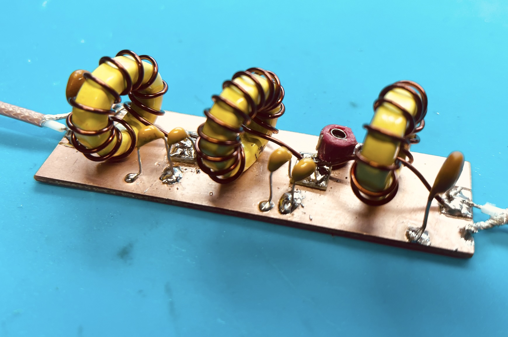
Construction
The filter is built on a strip of single-sided copper clad board, the same approach used throughout this build. The copper serves as the ground plane; capacitor leads and toroid tails solder directly to it, with small islands cut into the board for the non-grounded pads. This keeps the build compact and ground connections short — which matters at HF, where long leads add stray inductance that shifts the filter response.
The three toroids are wound with continuous lengths of magnet wire. Getting the turns tight and evenly spaced around the core helps with inductance accuracy. A turn counter while winding keeps the count honest.
NanoVNA Results
With the filter assembled, the NanoVNA confirmed what the design predicts.
The wideband sweep from 10 to 30 MHz shows the characteristic shape of a Chebyshev low pass filter: a flat passband through the 20m band, then a steep rolloff that is well into heavy attenuation by the time it reaches 28 MHz.

Zooming into the 20m band, the passband is flat with -1.18 dB insertion loss at 14.208 MHz and a measured SWR of 1.056. The impedance at that point is 47.6 − j1.0 Ω — essentially 50 ohms as far as the PA is concerned.

That is a well-behaved filter. The insertion loss is low, the match is good, and the stopband is where it needs to be.
Takeaway
With this filter in place, the 20m SSB transceiver build has all its building blocks assembled and individually tested. The next step is integration — getting everything onto a chassis, doing final alignment as a complete rig, and eventually putting it on the air. That is a satisfying place to be.
73 de EI9ITB